PLC Code
Return to PLCReturn to Code
Return to Portfolio
![]() The PLC programming language was written for electricians, who were typically
wiring switches and relays. To help them with the programming, a graphical style,
known as "Ladder Logic," was developed.
The PLC programming language was written for electricians, who were typically
wiring switches and relays. To help them with the programming, a graphical style,
known as "Ladder Logic," was developed.
The left hand and right hand vertical lines, shown in the lower left image, are known as the ladder rails they represent wires coming from a power source (like the battery in the upper image). The horizontal wires between the rails are known as the ladder rungs.
![]() The two short vertical lines, on the rungs, represent the switches; they are either normally
open (off) or normally closed (on). The coil (relay), on the right, is turned on, or off,
by the state of the switches inline with it.
The two short vertical lines, on the rungs, represent the switches; they are either normally
open (off) or normally closed (on). The coil (relay), on the right, is turned on, or off,
by the state of the switches inline with it.
Both images show the same logic; to power the coil, switch 2 must stay on (as shown) AND either switch 1 OR switch 3 must be also turned on.
The PLC program, shown below, is written in three distinct, and interlocking, states, which govern the
movement of the Stage Left and Stage Right "Rotators." The idea behind PLC programming as a
"state machine" is to make each "state" unique. This means, for the next state to begin,
all conditions must be met, including the previous states completion.
The entire execution of the program is done with the three buttons on the handheld control; forward, reverse and stop. There is only one user variable for the program - the speed control potentiometer. At any point in the sequence of moves, the units may be stopped, backed up, stopped again, and then continued forward once more. Therefore the actual number of individual programming states is sixteen: three forward and a completion stop, three reverse and a completion stop for each of the two units.
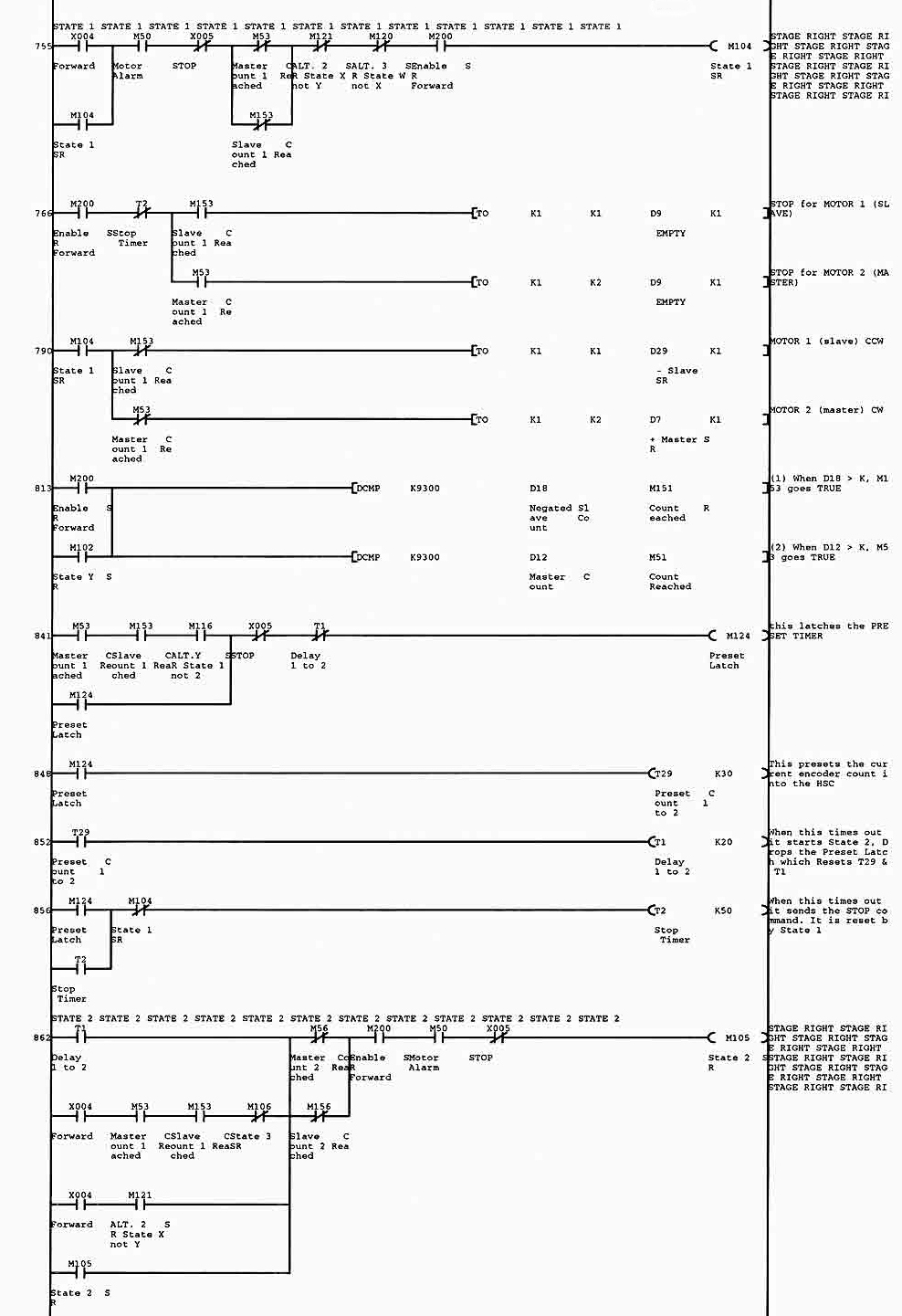
Ill try to describe the way line 755 works in the code image below. The goal of this line of code is simple; get the coil (m104) on the right to turn on, and stay on. This coil is used to allow the rest of the code in the "State One" section to work.
Starting from the coil on the right and moving left are conditions that have to be met in order for this coil to work (m 200) normally open, needs to be close. Its closed by earlier code, which says, All is ok to move.
Both (m 120) and (m 120) are normally closed. For the coil to turn on, they need to stay closed. Next are (m 53) and (m 153), they are shown in an "or" configuration. For the coil to get power, one or the other need to stay closed. These switches show the logic of an encoder count, if the count is reached, the switches will open.
The stop button on the hand held control is represented by switch (x 005), this is a normally closed switch, if pressed by the operator, it opens, cutting off power to the coil.
The next switch inline (m 50) is an alarm from the motors. If there was an electrical problem with the motors, the switch would not close.
The last two switches are also in "or" logic. The top one represents the forward button on the hand held control. Its whats known as a momentary switch, its on only for as long as the operator presses it.
A coil may have many switches associated with it as long as the coil (m 014) is on, the switch (m 014) is closed. The switch (m 104) as it is used here, is known as a latch, but the latch is broken if any of the switches inline to coil (m 104) change condition.
The condition Im looking for is the Master or Slave encoder count to be reached. When both counts are reached, the power flow to the (m 014) coil is broken, and turned off, there by disabling State One.
And thats the first line.