PLC Flow Chart
Return to PLCReturn to Code
Return to Portfolio
The scenery units the PLC and motors move are each roughly 24 feet wide, 36 feet
long and 32 feet tall. When the audience first sees them, the units are pushed
together, making a single piece 72 feet long. To show the other side to the
audience, the units have move in three basic steps:
In each unit are two DC drive motors, each with an electronic distance counter,
known as an encoder. One motor, and its encoder are labeled the Master, and the
other set are the Slave. In the movement of the scenery, the Master motor never
changes its rotational direction, however the Slave does.
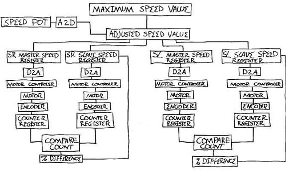
At the top of the chart is the maximum speed value - which is the maximum safe travel speed for the scenery, and is hard coded.
The operator can slow down or speed up the drive motor rate of travel with the speed potentiometer, up to the maximum speed allowed. That adjusted speed value is used by all four drive motors (two in each piece of scenery). At this point in the chart, the logic of the two sets of drive motors - the stage right set and the stage left set, is identical.
The entire movement of the scenery is governed by an encoder count. There are no limit switches, or proximity sensors that trigger events in the code. Since the slave encoders, and slave motors, change direction - counting down as well as up, I had to write code that kept track of the relative count of the slave count, and compared it to the absolute master count.
I added a close-loop feedback algorithm to synchronize the master and slave motor speeds. Due to space and budget constraints, I was never able to truly debug this as well as I'd like. But, as I've said - "It did work."
Return to PLCReturn to Code
Return to Portfolio
Top of Page