An LED-based fire lamp
(Last modified 8 Oct 11)
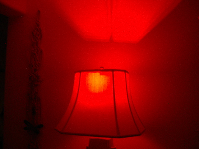
I call this a fire lamp because the LEDs, driven by an Atmel ATtiny85
MCU, provide a very realistic imitation of a flickering flame about the
size of a tennis ball. Unfortunately, I've never bothered to buy
a video camera, so I can't embed any live video. However, the
flickering effect is excellent, without any strobing or blinking.

I used the Liteon LTL912SEKSA Piranha red LEDs for this build.
These LEDs are available (Oct 2011) from Electronic Goldmine for $0.39
each. Unlike typical 3 mm or 5 mm LEDs, these device will take up
to 70 mA each, have a wide dispersion angle of 60 degrees, and put out
nearly four lumens. They are commonly used in automobile brake
lights and make a totally excellent light source for light art.

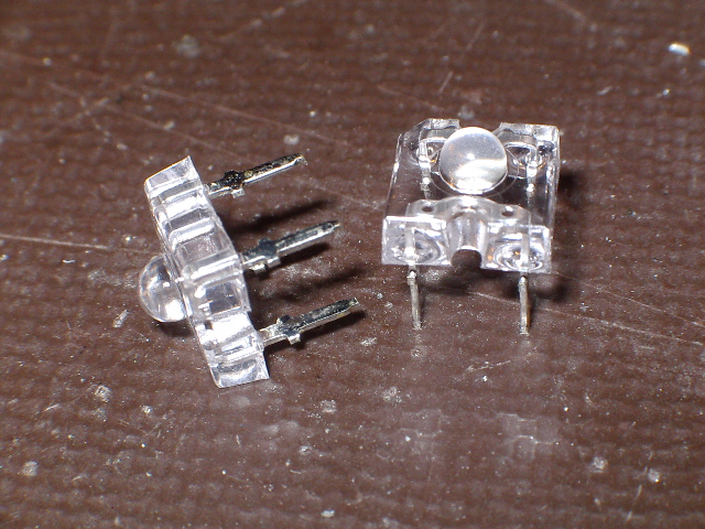
Closeup of the Liteon Pirhana LEDs. Note that the pins are in a
square pattern, spaced 0.2" apart.
The circuit is slightly more complex than a typical LED driver because
of the LED current. The ATtiny can't source the needed 60 mA per
LED, so I added a 2N2222 transistor in each LED control line. You
can use just about any NPN transistor for this if you can't find any
2N2222 or PN2222 devices. You can check out the schematic
here. (firelamp.pdf)
The schematic includes a note for changing resistor values to use
smaller (less current) LEDs.
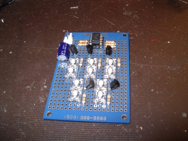
I built the circuit up on a small breadboard, adding a 2-pin power
connector for hooking up a wall-wart power supply. You can find
small, 5 VDC switcher wall-warts in a lot of surplus or thrift stores
now days; these make excellent power supplies for small projects.
You can tell you're holding a switcher wall-wart because it will be
very lightweight, only a few ounces. If you hook it up to AC and
measure the output, you will see a value from about 4.9 to 5.1 VDC,
unlike the 6 to 9 VDC put out by some of the older, unregulated (and
heavier) wall-warts.

The circuit fits onto a 2" x 3" protoboard with plenty of room to
spare. The capacitor C1 is shown as 25 uf, but just about
anything between 10 and 1000 uf will work.
Using a small wall-wart and an old-fashioned socket plug lets you
install the firelamp circuit board directly in a table lamp
socket. This gives you a table lamp that looks like it has a
small fire in it, rather than a bulb (which explains the project's
name).

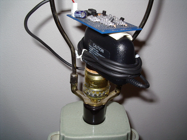
Here is the firelamp PCB and wall-wart, plugged into a socket plug and
installed in a table lamp. I stuck the PCB onto the top of the
wall-wart using foam tape, but hot-glue or RTV would probably work, as
well. I didn't shorten the power cord on the wall-wart, just
wound it around the body and tied it in place.
The firmware for this project was written in C in Atmel's AVR Studio4,
then pushed into the ATtiny using an AVRISP mkII programmer. The
only tricky part of the firmware is the technique for doing pulse-width
modulation (PWM) for the LEDs. I am really fussy about LED
PWM. I don't want to see any strobing when my eyes scan past the
LEDs. For this project, I used a PWM clock of 1 MHz / 256, or
about 4 kHz. Each LED is controlled by a 32-bit PWM mask.
At each PWM clock (4000 times per second), the low bit of each LED's
PWM mask is written to the output port for that LED. Intensity of
each LED is varied by a different PWM mask from the table of 32
possibilities. For example, using a PWM mask value of
0x55555555UL will give an LED intensity of about 50%, since the LED is
on every other PWM clock.
Feel free to play around with the timing. You can modify the
timer setup to use a compare-match instead of the overflow shown here,
which would let you use an even faster PWM clock rate.
Here is a .hex file you can burn directly into an ATtiny85 if you don't
want to be bothered compiling. (firelamp.hex)
/*
*
firelamp.c PWM control of LEDs on an
ATtiny85
*/
#include <avr/io.h>
#include
<avr/pgmspace.h>
#include
<avr/interrupt.h>
#define
NUM_LEDS 6
#define
MASK_LEDS
0x3f /* assumes PB0 - PB5 */
#define
NUM_PWM_STATES 32
#define
MAX_PWM_STATE (NUM_PWM_STATES-1)
#define
PORT_LEDS PORTB
#define
DDR_LEDS DDRB
#define
DELAY
1000UL /*
general delay in tics */
const unsigned long
int pwmvals[NUM_PWM_STATES]
PROGMEM =
{
0x00000000L, 0x00010000L,
0x00010001L, 0x80200800L,
0x01010101L, 0x82080820L,
0x84108410L, 0x84112410L,
0x11111111L, 0x11249111L,
0x12491249L, 0x25225252L,
0x25252525L, 0x25525522L,
0x25552555L, 0x25555555L,
0x55555555L, 0x55575555L,
0x57555755L, 0x57575755L,
0x57575757L, 0x57577775L,
0x57777577L, 0x57777777L,
0x77777777L, 0xf7777777L,
0xf777f777L, 0xf7f7f777L,
0xf7f7f7f7L, 0xf7fff7f7L,
0xf7fffff7L, 0xffffffffL
};
uint8_t
bright[NUM_LEDS];
uint8_t
delta[NUM_LEDS];
uint32_t
pwm[NUM_LEDS];
uint16_t
delays[NUM_LEDS];
volatile
uint16_t
tics[NUM_LEDS];
/*
* Local functions
*/
uint16_t
readtics(uint8_t cntr);
void
writetics(uint8_t cntr,
uint16_t delay);
void
assignpwm(uint8_t led);
static long unsigned int
b_random(void);
static long unsigned int
rnd(long unsigned int val);
int main(void)
{
uint8_t
n;
unsigned long
int nval;
TCCR0B =
(1<<CS01);
// /8 prescaler
TIMSK =
(1<<TOIE0);
// enable interrupt on TOF
PORT_LEDS =
PORT_LEDS & ~MASK_LEDS; //
turn off all LEDs
DDR_LEDS =
DDR_LEDS | MASK_LEDS; // make all
LED drive lines outputs
for (n=0;
n<NUM_LEDS; n++)
{
bright[n] = 0;
// start with all brightness values at 0
assignpwm(n);
// make it so
delays[n] = 200;
// start with an arbitray delay value
}
sei();
// turn on
interrupts
while
(1)
// main loop
{
for (n=0; n<NUM_LEDS; n++)
// for each LED
{
if (readtics(n) ==
0) // if done
with current delay for this LED...
{
nval = rnd(20)
+ 11;
bright[n] =
nval & 0xff; // update the brightness
assignpwm(n);
nval =
rnd(750) + 250; // calc a random
delay
writetics(n,
nval & 0xffff);
}
}
}
return 0;
}
void
assignpwm(uint8_t led)
{
cli();
// do not
disturb
pwm[led] =
pgm_read_dword(&pwmvals[bright[led]]);
sei();
}
uint16_t
readtics(uint8_t cntr)
{
uint16_t t;
t = tics[cntr];
if (t !=
tics[cntr]) t = tics[cntr];
return t;
}
void
writetics(uint8_t cntr, uint16_t delay)
{
cli();
tics[cntr] =
delay;
sei();
}
/*
* The following
functions try to duplicate the ANSI random() function for 8-bit MCUs
such as the
* Atmel
ATmega1284p. Seed is fixed at compile time.
*/
static long unsigned int
b_random(void)
{
static long
unsigned int
seed = 12345678L;
seed =
1664525L * seed + 1013904223L;
return seed;
}
static long unsigned int
rnd(long unsigned int val)
{
long unsigned
int
t;
t =
b_random();
// compute a 32-bit random number
val = t % val
+ 1L;
// now keep it
within requested range
return
val;
}
SIGNAL(TIM0_OVF_vect)
{
uint8_t n;
uint8_t mask;
uint32_t t;
mask = 0;
for (n=0;
n<NUM_LEDS; n++)
// for LED 0 through NUM_LED-1...
{
t = pwm[n] & 1;
// get low bit of PWM for this LED
mask = mask | (t << n);
// move low
bit of PWM into proper bit of mask
pwm[n] = (pwm[n] >> 1);
// move PWM
value one bit to the right
if (t) pwm[n] = pwm[n] +
0x80000000; // rotate original low bit into high bit
if (tics[n]) tics[n]--;
// drop this
counter if not yet 0
}
PORT_LEDS =
PORT_LEDS & ~(MASK_LEDS); // strip off port lines
dedicated to LEDs
PORT_LEDS =
PORT_LEDS | mask;
// turn on the LEDs
}
Home