Hacking
a RainBird drip irrigation controller
(Last
updated 3 May 2020)
The RainBird drip irrigation controller has a lot to offer the
hobbyist/hacker. It runs a year on a pair of AA batteries, has
a large LCD screen and accurate clock/calendar, and sports a simple
UI based on a six-position rotary dial, all packed into a rugged,
waterproof housing. You would be hard pressed to design and
build something to match for anywhere close to the retail price of
about $30.
The key to making this piece of gear control your own electrical
project involves replacing its water-valve solenoid with circuitry
that will trigger your add-on when the time is right.
Fortunately, this circuitry is minimal and easy to cobble together.
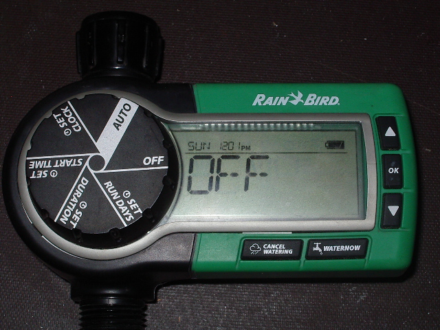
Here is a typical RB drip irrigation controller. You've got
your big LCD screen, your battery indicator, your six-step mode
selector wheel, and your pushbuttons, all in a rugged case.
What more could you need?
Starting
Begin by removing the five screws from the back of the device,
then removing the back cover.
The solenoid is connected to the electronics subassembly (housed
inside the front panel) with a short harness containing one red wire
and one white wire.
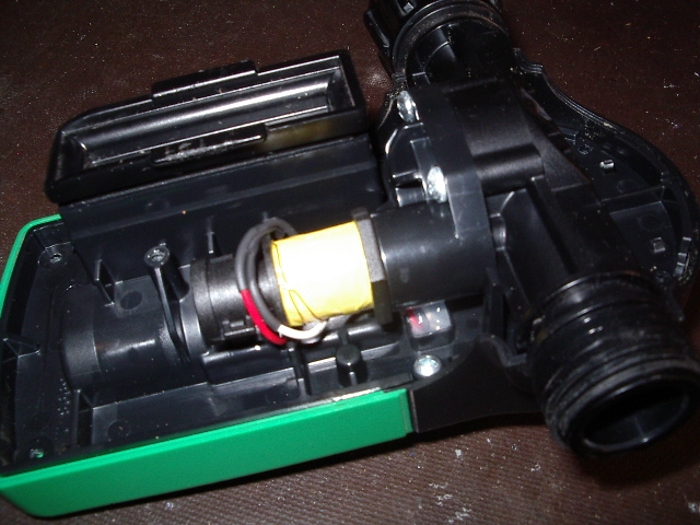
I've removed the back cover, exposing the solenoid (yellow) and the
two wires that control it. The solenoid is built into a
water-valve assembly.
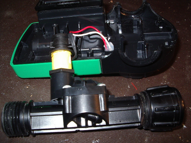
I've removed the water-valve assembly from the main unit (it just
unclips with a pair of plastic tabs); you can see the red wire and
white wire that we will use for controlling our own circuitry.
Clip these wires near the body of the solenoid, then set the
solenoid and water-valve assembly aside. Everything we need
for this project is in the front panel assembly.
The device's MCU controls the solenoid by issuing a short, positive
pulse to turn the water valve on and a short, negative pulse to turn
the water valve off. Specifically, the ON pulse is about 20
VDC and 25 msecs in duration, while the OFF pulse is about -20 VDC
and also 25 msecs in duration. Note that these voltages were
measured using the white wire as reference.
If you are adept with MCUs, you can easily add a resistor divider to
knock the ON pulse down to 5 or 3.3 VDC, then wire the signal to an
interrupt line on an MCU. You would have either to block the
negative pulse with a diode, or to run both pulses through a diode
bridge to turn the OFF pulse into a positive-going signal.
Then you just need some code to handle the interrupt when the pulses
hit, and you are ready to use the RB timer in your project.
But there is a large group out here who could use this kind of
powerful timer but lack the embedded design chops to do what I just
described. We need a general-purpose hack that lets someone
wire a relay to the RB controller and immediately start controlling
their chicken coop door or time-lapse camera or whatever.
The circuit
Here is a small circuit that will convert the short ON pulse
into a longer-duration, open-collector output, suitable for
controlling a low-current device such as a 12 VDC relay.
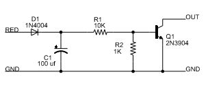
The signal named RED refers to the red wire connected to the front
panel (underneath a wad of sealing goop). The signal named GND
(on the left side of the schematic) refers to the white wire
connected to the front panel, also under the goop. If you clip
these wires near the body of the solenoid, you should have about
three inches of wire length to work with.
D1 blocks the negative-going OFF pulse; this circuit only converts
the ON pulse. C1 and R1 act as a small power supply,
converting the charge from the 25 msecs ON pulse into a voltage to
turn on Q1; this causes the OUT signal to go to ground. It
takes about 350 msecs for the voltage on Q1's base to drop below 0.7
VDC, which turns off Q1 and forces the OUT signal to high
resistance, relative to GND.
Parts are not critical. Q1 can be any general-purpose NPN
switching transistor; 2N2222A or similar should work.
Resistors are 1/4 watt or less. C1 will see a short pulse in
the 20 VDC range, so anything 25 VDC or higher should work. D1
can be nearly any general-purpose power diode; anything in the
1N400x family should be fine.
This circuit does not draw any additional current from the RB's AA
cells, beyond that used to fire the solenoid. This means you
should get the same life from the batteries that you would get using
the RB controller as intended.
The circuit is a typical open-collector driver, and you have a lot
of options for your output device. To use this circuit to
control a relay, wire the negative terminal of the relay coil to
OUT, then wire the positive terminal of the relay coil to the
positive terminal of a power supply that matches the relay's coil
(such as 12 VDC, but check your relay to be sure). Finally,
wire the negative terminal of the power supply to GND.
Building the circuit
You could build this circuit on a small breadboard, but there
are so few components that I just wired it up point to point.
Time for some testing
Insert a pair of AA batteries into the RB battery pack, then
insert the pack into the RB unit. The display should do a
quick selftest, then prompt you to set the time.
If you wired up a relay as described above, you are ready to
test. If you want to test with an LED, connect a small battery
pack or bench supply to your RB circuit by wiring the supply's GND
lead to the circuit's GND wire and the supply's output to a load,
such as the anode of an LED plus current-limiting resistor.
Then wire the other lead from the load to the OUT wire. For
example, you could use a 12 VDC supply, a white LED and 1K-ohm
limiting resistor for this test.
Press the WATERNOW button on the front panel; the display should
prompt you to press OK. Press the OK button. After a
second or so, the relay should click or the LED should flash.
The display should also show a countdown timer starting from 10
minutes.
Press the CANCEL WATERING button on the front panel. The relay
should not click and the LED should not flash, but the RB should
cancel the countdown timer and revert to prompting you to set the
time.
Cleanup
There is not much left. Add a wire to the GND lead and a
wire to the OUT lead and terminate them however works best for
you. One option would be a simple wire harness exiting through
a hole drilled into the side of the case (provide some sort of
strain relief so you can't damage the circuit by pulling on the
harness). You could also cut or drill a mounting hole in the
side of the cover and mount your own form of two-wire connector.
Once you have the termination added, close up the case using the
five screws you removed originally. Note that there will be a
large hole in the top and the bottom of the cover, where the water
valve used to fit. If your application requires
weatherproofing or protection against the elements, you will need to
plug or cover these holes. Alternatively, you could just
reinstall the water-valve assembly; after all, it was designed to
protect the interior.
At this point, you can use the RB UI to set the time/day and enter
an event schedule. Refer to the RB manual or website for
details, although setup is pretty intuitive.
Finally, switch the RB to Auto mode and it will begin following your
schedule. Each time the RB "turns on the water", it will
momentarily close the relay you have wired up. Each time the
RB "turns off the water", nothing will happen. WATERNOW turns
on the water, and can be used to create a relay closure manually
from the front panel. This can be important if your load ever
gets out of sync with your RB schedule.
Options
Of course, there are options! This circuit ignores the OFF
pulse. If you want to use the OFF pulse also, replace D1 with
a diode bridge assembly. Wire the RED and WHT wires to the
bridge's AC side, then connect the GND wire to the bridge's negative
side and C1's positive terminal to the bridge's positive side.
However, using both the ON and OFF pulses can make using this device
in the real world tricky. For example, say you have this
hooked up to control a chicken coop door. You need to ensure
that the coop door is closed when the RB sends an ON pulse. If
the coop door is already open, then the door will be out of sync
with the controller's ON pulse. You could use the WATERNOW
button to force an ON pulse, but eventually, the RB will follow this
with an OFF pulse and you're back where you started.
The above sections talk about using Q1 to control a relay.
However, you may need more than a 350 msecs relay closure for your
project. You can find a number of latching relay devices on
Amazon for about $15. Any such device that needs a voltage
pulse on an input to toggle the state of the latching relay should
work fine here. Just wire the latching relay's input up as if
it were a relay, as described above. Some latching relay
boards only need a momentary short circuit between an input and
ground, like a button press. I have not used any of these
boards, but I suspect hooking the OUT signal to the relay board
input and the GND signal to the relay board ground should
work. If you try this before I do, please let me know which
relay board you used and how it turned out.
I chose a 350 msecs pulse width on the output because that seemed
like a reasonable delay for most projects. You can use
different values of C1 and R1 to modify the pulse duration, within
limits. You don't have a lot of power to work with here, as
the original pulse is so short. But try larger values of C1
and/or R1 to get a longer pulse duration, if needed.
Note that the leading (falling) edge on OUT will be square at the
top and at the bottom, but the trailing (rising) edge will have a
definite RC curve to it. R2 is intended to reduce that rise
time, but the rise time is also influenced by the chemistry of the
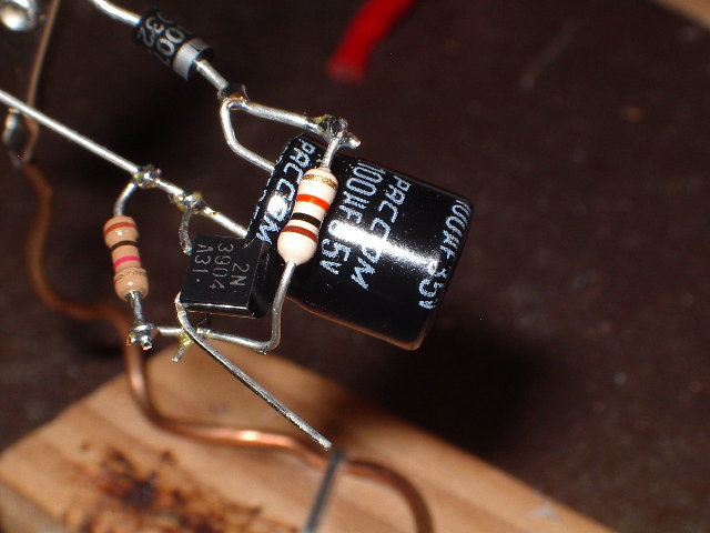
capacitor at C1. The PACCOM cap used above had a rise time of
nearly 200 msecs, but a Nichicon cap of the same rating had a rise
time around 50 msecs. If your intended use needs a fairly fast
rise time, you might have to experiment with different caps to get a
good match.
Caveats
Based on Amazon reviews of May, 2020, the RB controller shown
above appears to have some issues. Users (myself included)
have reported that the device stops turning off the water after a
season or so of use; I think mine lasted two years. In my
case, the solenoid would click to turn off, but the water would
continue running. This actually works in my favor, since now I
have a RB controller with working electronics that I can hack!
Others have reported that the electronics simply stops working after
they replace the batteries. Here, "stops working" means the
display shows a single horizontal line across the width of the
display and no text. I saw this happen with my unit, also, but
this was actually easy to fix. Remove the battery pack and
look inside the battery compartment of the RB unit. You will
find two small metal tabs down near the bottom of the
compartment. Use a small screwdriver or dental pick to pry
each of these tabs slightly away from the wall of the battery
compartment. Work carefully so you don't snap a pad off; you
only need to move these pads maybe 50 mils or so. Put the
battery pack back in and the unit should wake up.
Done
The RB controller is just too well designed and rugged not to
hack. I hope the above information helps you get started on
your own timer-based controller project. Have fun!
Home