(Last modified 4 Dec 09)
I picked up a couple of green laser pointers from a vendor on Amazon in late November, 2009; here is the link. I wanted these lasers to use in some light-show experiments, so actual optical output power wasn't crucial; I just wanted them way brighter than the 5 mW red laser I'm currently using.
The green laser pointers are sold as 50 mW and have a tag that says the optical output power is < 50 mW, but I have no way of knowing exactly what it is. But they are plenty bright enough for my uses, and at $19 each, I'm happy.
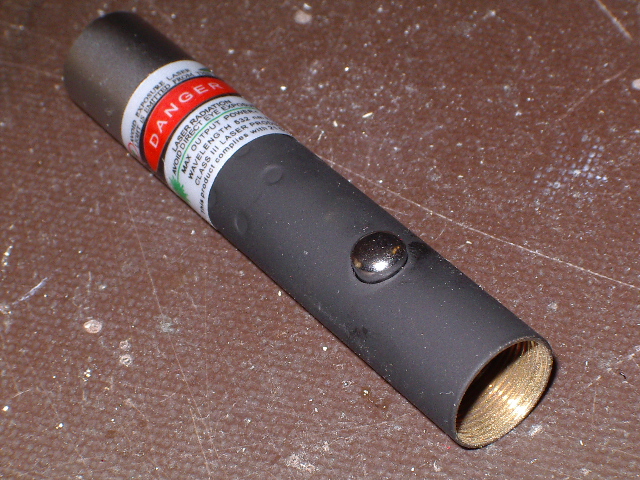
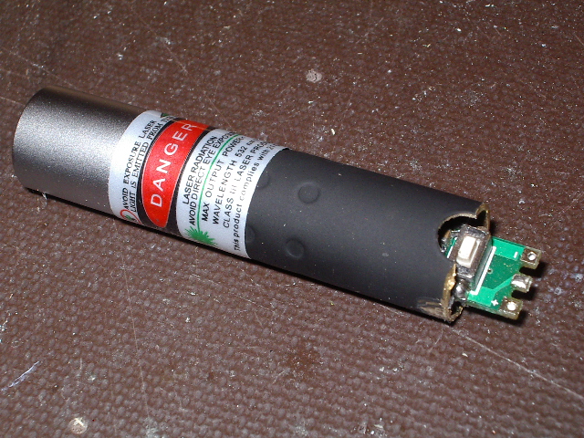
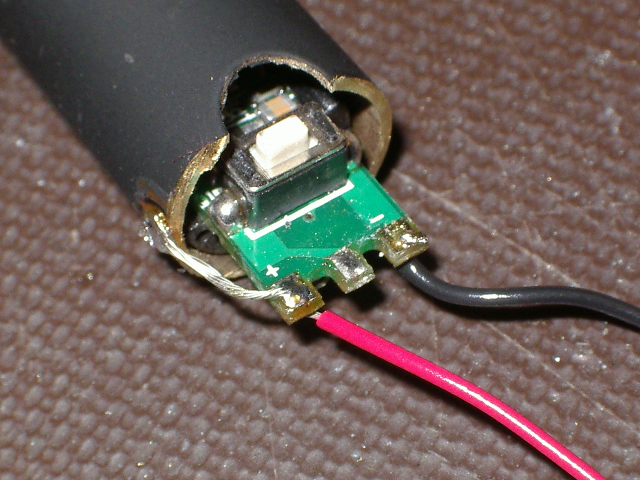
However, I wanted to change them a bit (naturally!). Rather than run from the normal two AAA batteries, I wanted to hook them to a regulated 3 - 3.3 VDC. Since I didn't need the batteries, I also wanted to get rid of the battery case and make the laser module as short as possible. The pictures below show what I did.
WARNING!
The following procedure is quite delicate! Use caution and
work carefully! If you rush this work or aren't careful,
you could easily destroy your laser pointer!

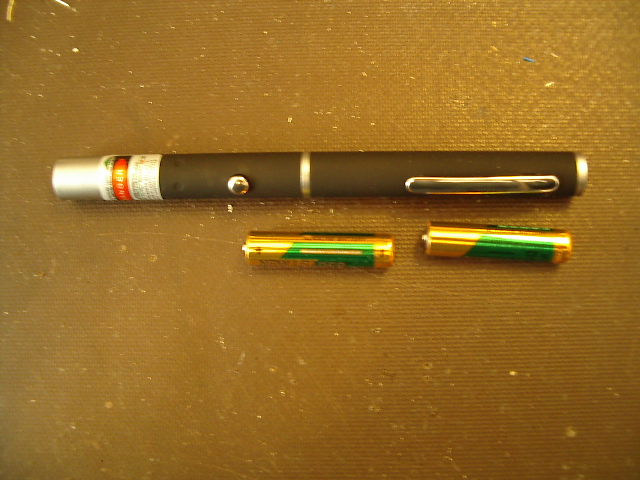
First off, above is a picture of the laser pointer as I received it. The laser pointer wants the batteries installed with the positive end to the right (opposite of what's shown here). This means that the metal barrel of the laser pointer is connected to the positive terminal of the battery. This is important, as you'll see later on. If your laser pointer uses the batteries in the reversed configuration (negative terminal to the barrel), you will need to change a step below.
The following procedure is quite delicate! Use caution and
work carefully! If you rush this work or aren't careful,
you could easily destroy your laser pointer!

First off, above is a picture of the laser pointer as I received it. The laser pointer wants the batteries installed with the positive end to the right (opposite of what's shown here). This means that the metal barrel of the laser pointer is connected to the positive terminal of the battery. This is important, as you'll see later on. If your laser pointer uses the batteries in the reversed configuration (negative terminal to the barrel), you will need to change a step below.


