Bare-metal mbed; connecting to the Gameduino
(Last modified
3 Jan 2012)
I have a Gameduino
and I have an mbed; guess what's next...
For those who don't know, the Gameduino is a small board that takes SPI
data in from virtually anything and provides VGA signals out.
Runs on 3.3 VDC, takes about 25 mA of current, runs at an SPI clock of
up to 8 MHz, and provides a wealth of graphics coolness. Check
the home page above for lots more info.
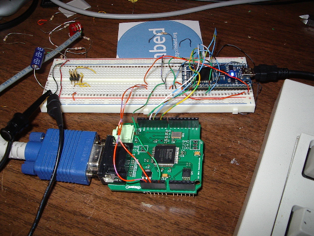
First off, here is my lashup
development platform...

Yeah, that's not the most robust wiring hookup, but it's good enough
for test purposes. The mbed is plugged into the white
experimenter's board and the Gameduino is the green Arduino shield in
the foreground. I'm powering the mbed from the USB cable, then
using the mbed's 3.3 VDC output on pin 40 to power the Gameduino.
Note that I hooked 3.3 VDC to both
the 3.3 VDC and 5 VDC inputs on the Gameduino.
I really bought the Gameduino (that's a wad to type; I'll call it GD
for now) so I could put text on a VGA monitor from a small MCU.
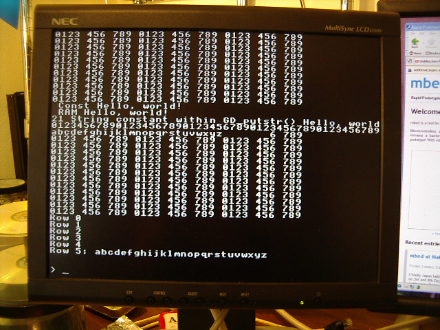
So no fancy graphics in this write-up; here's some text on a 15" NEC
MultySync monitor...

The code supplied by the GD website is in C++, using typical
object-oriented programming techniques. I usually work in C, so I
recoded the class library as C functions. This file, called
gdsupport.c, also contains a custom function that allows me to keep the
support functions target-independent. The main program (in
gd_test.c) calls a support function named GD_register() and provides
pointers to the three target-specific functions needed for GD
support. These are _select(), which enables the SPI connection to
the GD, _xchg(), which exchanges a single byte of data with the GD, and
_deselect(), which disables the SPI connection. Code in the
gd_test program is invoked through these function pointers whenever the
support library needs to exchange data with the GD.
Here is the entire gd_test.c program, showing the mbed and Gameduino
setup and the technique for displaying text on the VGA screen:
/*
* gd_test.c test platform for
playing with the Gameduino
*
* This program allows the mbed development board to control
a Gameduino
* via SPI.
*
* The code here initializes the Gameduino, then displays
ASCII text on
* the GD's VGA screen. I developed this primarily as
a way to play with
* text on the GD, since the rest of the world is using the
GD for graphics. :-)
*/
#define OWNER
#include <stdio.h>
#include <string.h>
#include <errno.h>
#include "LPC17xx.h"
#include "gdsupport.h"
/*
* I'm going to be the owner of errno (the global error
number variable),
* so I need to undefine it here, then redefine it as an
int. All other
* modules that link with me must do the same, declaring
errno as extern.
*/
#undef errno
int
errno;
/*
* Rather than put target-specific SPI code inside this
module, I use
* a set of three routines that are target-specific, then
rely on the
* gdsupport module to do all of the non-specific SPI
operations.
*
* This works through the following three callback
functions. test_select()
* is called by the gdsupport code to select the
Gameduino. test_xchg()
* is called to exchange a byte of data with the GD.
test_deslect()
* is called to deselect the GD.
*/
void
test_select(void);
unsigned char
test_xchg(unsigned char);
void
test_deselect(void);
/*
* outstr() is a wrapper function that lets me display a
null-terminated
* string on the GD's VGA screen using the Gameduino outch()
function.
*/
void
outstr(char *s);
unsigned int
SystemCoreClock;
// global
variable, core clock frequency
/*
* Use P0.16 as chip-select for the GameDuino.
*/
#define GD_CS_BIT
16
#define GD_CS_MASK
(1<<GD_CS_BIT)
#define GD_ENABLE
(LPC_GPIO0->FIOCLR = GD_CS_MASK)
#define GD_DISABLE
(LPC_GPIO0->FIOSET = GD_CS_MASK)
/*
* The following strings are stored and initialized two
different ways. HelloConst
* is read direcly from read-only data (.rodata) while
HelloRam is copied from
* flash to RAM and read from RAM (.data).
*
* These strings are here to confirm proper operation of the
linker script that
* builds this program.
*/
const char
HelloConst[] = " Const Hello,
world!
";
char
HelloRam[]
= " RAM Hello,
world!
";
/*
* init perform low-level
initialization of the mbed board
*
* main() must call this routine before doing any other
major tasks on the mbed!
*/
void init(void)
{
/*
* Clock initialization for the Mbed development
board. This board
* uses a 12 MHz oscillator as the main clock source.
This code
* sets the core clock to 96 MHz.
*/
LPC_SC->SCS = 0x20;
//
enable external oscillator (12 MHz crystal)
while (!(LPC_SC->SCS & (1<<6)))
; // wait for main oscillator to stablilize
LPC_SC->CLKSRCSEL = 0x01;
// set main oscillator (12 MHz
crystal) as PLL source
LPC_SC->CCLKCFG = 0x03;
// set CPU clock (CCLK) to
PLL0 output / 4
LPC_SC->PCLKSEL0 = 0x0;
// peripherals use CPU
clock / 4
LPC_SC->PCLKSEL1 = 0x0;
// peripherals use CPU
clock / 4
/*
* The following code sets up the Mbed's core clock to 96
MHz.
* This code sets PLL0 output to 384 MHz. The CPU clock
* configuration above (CCLKCFG) divides this value by 4
* to get a final CPU clock of 96 MHz.
*/
LPC_SC->PLL0CFG = (0<<16) |
(15<<0); // PPL0 config, M=16, N=1, Fout=384
LPC_SC->PLL0FEED = 0xAA;
// feed the PLL
LPC_SC->PLL0FEED = 0x55;
LPC_SC->PLL0CON = 0x01;
// enable PLL0
LPC_SC->PLL0FEED = 0xAA;
// feed the PLL
LPC_SC->PLL0FEED = 0x55;
while (!(LPC_SC->PLL0STAT &
(1<<26))) ;
// wait for PLL0 lock
LPC_SC->PLL0CON = 0x03;
// enable and connect PLL0
LPC_SC->PLL0FEED = 0xAA;
// feed the PLL
LPC_SC->PLL0FEED = 0x55;
while (!(LPC_SC->PLL0STAT & ((1<<25) |
(1<<24)))) ; // wait for PLL0 enable and
connect
SystemCoreClock = 96000000;
// need to make this value available globally
/*
* Set up PLL1 for use as a USB clock. The output must
be set to 48 MHz, based
* on an oscillator of 12 MHz.
*/
LPC_SC->PLL1CFG = 0x00000023;
// PLL1 config, M=4 (bits 4:0=3), P=2 (bits 6:5=1)
LPC_SC->PLL1FEED = 0xAA;
// feed the PLL
LPC_SC->PLL1FEED = 0x55;
LPC_SC->PLL1CON = 0x01;
// enable PLL1
LPC_SC->PLL1FEED = 0xAA;
LPC_SC->PLL1FEED = 0x55;
while (!(LPC_SC->PLL1STAT &
(1<<10))) ; // wait
for PLL1 lock
LPC_SC->PLL1CON = 0x03;
// enable and connect PLL1
LPC_SC->PLL1FEED = 0xAA;
// feed the PLL
LPC_SC->PLL1FEED = 0x55;
while (!(LPC_SC->PLL1STAT & ((1<<9) |
(1<<8)))) ; // wait for PLL1 enable and connect
}
int main(void)
{
int
n;
init();
// do low-level setup first!
/*
* Configure the SPI port for connection to the Gameduino.
*/
LPC_SC->PCONP |= (1<<8);
// apply power to the SPI interface
LPC_SC->PCLKSEL0 |=
(1<<16);
// use CCLK as SPI clock
LPC_SPI->SPCCR = 24;
// now divide SPI clock by this
much (must be >= 8, must be even!)
LPC_PINCON->PINSEL0 |=
(3<<30);
// set P0.15 as SCK (collides with UART1 TXD1)
LPC_PINCON->PINSEL1 |=
(3<<2);
// set P0.17 as MISO (collides with UART1 CTS1)
LPC_PINCON->PINSEL1 |=
(3<<4);
// set P0.18 as MOSI (collides with UART1 DCD1)
LPC_PINCON->PINMODE1 |=
(2<<2);
// set MISO with no pull-up or pull-down
LPC_SPI->SPCR = (1<<5);
// set SPI to master mode
LPC_GPIO0->FIODIR |=
GD_CS_MASK; //
use SSEL as GPIO slave select line; make it an output
GD_DISABLE;
// pull
the chip-select line high
/*
* The SPI is set up. Now we need to register our
callback functions
* with the Gameduino support module.
*/
GD_register(&test_select, &test_xchg,
&test_deselect);
/*
* All done, strut our stuff!
*/
GD_begin();
// set
up the GD hardware
GD_ascii();
// set
up for using text
GD_cls();
for (n=0; n<100; n++)
// use the GD_outch function...
{
outstr("0123 456 789 0123 456 789
0123 456 789\n\r");
}
/*
* Use the direct-write functions in the GD library.
*/
GD_putstr(0, 19, HelloConst);
GD_putstr(0, 20, HelloRam);
GD_putstr(0, 21, "21 String constant within
GD_putstr() Hello, world!");
GD_putstr(0, 22,
"012345678901234567890123456789012345678901234567890");
GD_putstr(0, 23,
"abcdefghijklmnopqrstuvwxyz ");
/*
* Use some local functions that in turn use the GD_outch
library function.
*/
outstr("Row 0\n\r");
outstr("Row 1\n\r");
outstr("Row 2\n\r");
outstr("Row 3\n\r");
outstr("Row 4\n\r");
outstr("Row 5: abcdefghijklmnopqrstuvwxyz\n\r");
outstr("\n\r");
outstr("\n\r> ");
while (1) ;
return 0;
}
/*
* test_select callback
function; selects GD adapter
*/
void test_select(void)
{
GD_ENABLE;
}
/*
* test_xchg callback
function; exchanges a byte with GD adapter
*/
unsigned char test_xchg(unsigned char val)
{
unsigned char
c;
LPC_SPI->SPDR = val;
// send a byte
while ((LPC_SPI->SPSR & (1<<7)) ==
0) ; //
loop until data reg is empty
c = LPC_SPI->SPSR;
// NXP says read this one more time!
return LPC_SPI->SPDR;
//
return the result
}
/*
* test_deselect callback
function; deselects GD adapter
*/
void test_deselect(void)
{
GD_DISABLE;
}
/*
* outstr quick-and-dirty
string print function
*/
void outstr(char *s)
{
while (*s)
{
GD_outch(*s);
s++;
}
}
The init() function above configures the mbed for a core clock of 96
MHz, then sets up an SPI connection at 4 MHz, which is well below the 8
MHz listed as the
top-end for the GD. I"ve chosen to use the LPC1768's SPI
subsystem, rather than either of the SSPs.
After configuring the SPI, I call GD_register() to provide pointers to
the three SPI support functions, test_select(), test_xchg(), and
test_deselect(). Once that's done, the rest of the code is
plain-vanilla GD function calls
I've put all of the files used in creating this project into this zip file. If you want to rebuild,
you will need a setup similar to what I've described elsewhere in this
site for bare-metal work using CodeSourcery and Visual Studio
2005. If you don't want to rebuild but just want to watch the
program run, I've included the .bin file as well; all 5.5 KB of
it. :-)
Home