Replacing the Raspberry Pi's Main Voltage Regulator
(Last modified 6 Jul 2012)

This mod is based on the project here (http://www.bitwizard.nl/wiki/index.php?title=Reducing_power_consumption_of_a_raspberry_Pi), which was featured in a recent Hackaday post.  However, I wanted the entire mod left on the RasPi PCB, plus I wanted to see for myself how much current reduction I would get.  So I set out to make my own version of this hack.

Obviously, this hack is going to void any warranty and risks damaging your precious RasPi; you take on this hack at your own risk!  If you are unsure about removing or soldering components on the PCB, skip this mod or hand it off to someone more experienced.

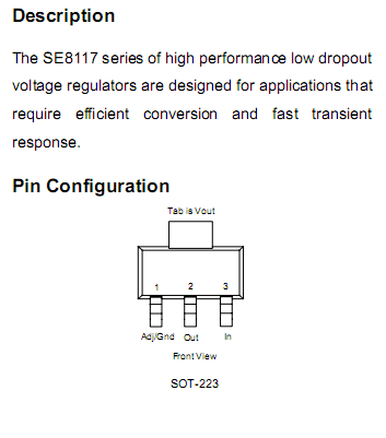
The stock regulator (RG2) is a low drop-out SE8117 from Seaward Electronics, Inc.; you can find the docs with some Googling.  Here is the relevant bit:

Pinout for the SE8117 regulator

Note that on the RasPi PCB, there is no pad for pin 2; that connection is made through the heatsink tab.

The stock RasPi regulator

Here is a closeup of the stock regulator (RG2) on the RasPi board.

The first step is removing the SE8117 from the PCB.  I clipped the leads on pin 1 and pin 3 using fine-tipped wire cutters.  Work carefully on this step; you don't want to twist or torque the leads as you cut them or you might damage one of the pads.

SE8117 after clipping pin 3

Here you can see where I've clipped pin 3 off of the regulator.  Use a solder iron to remove the fragments of component lead still soldered on the pads for pins 1 and 3.

Removing the body of the regulator is a bit more difficult.  The large thermal mass makes it hard to unsolder this device with most fine-tip soldering irons.  I pulled out my trusty Weller 8200 100W soldering gun and had the part unsoldered in a matter of seconds.  Be sure to get the part hot enough so it slides around on the solder before you remove it.  Do NOT try to pry off this part without heating it sufficiently; you could damage the thermal pad underneath it.

Ready to add the new regulator

Here is where I will connect the replacement regulator board.


The Pololu D24V6ALV regulator
With the footprint for RG2 empty, it is time to add a replacement regulator.  I chose the Pololu D24V6ALV device, a dime-sized, adjustable-output buck regulator with up to 600 mA output current.  This unit has a very tiny potentiometer on it, letting you adjust output between 2.5 and 7.5 VDC, depending on the input voltage.  In this case, I will be supplying 5 VDC and I will need to dial in the regulator to provide 3.3 VDC output.  This will replace the original SE8117.

Note that the Pololu board has four connection pads, one of which is labeled *SHUTDOWN.  When you wire up this PCB, you must tie the *SHUTDOWN pin to VIN to turn on the regulator.  If you leave off this connection, the regulator will not turn on and the output will be 0 VDC.

I hooked the regulator PCB to my bench supply and fed 5 VDC into VIN and GND.  With a DVM on the VOUT pad, I used a jeweler's screwdriver to adjust the PCB's potentiometer for 3.3 VDC output.  Note that this is a delicate control, so work carefully and try not to overwork the potentiometer.  It looks kind of fragile and I don't know how many tweaks you will get before it breaks.

I added short, color-coded leads to the VIN, VOUT, and GND pads of the regulator PCB, making sure that I tied VIN to *SHUTDOWN.  I then soldered these leads to the RasPi PCB, using the pin configuration above as a guide.

The RasPi PCB has a nice, open area immediately above the RG2 footprint, perfect for mounting the Pololu regulator with a bit of foam tape.  It hides the cute Raspberry Pi logo, but I consider that a small price to pay.  :-)

The Pololu regulator installed

Here you can see the replacement Pololu regulator board installed and ready to go.

I reassembled my RasPi Model 100, hit the power switch, and watched as my cooler RasPi went through the boot sequence.


But how well does it work?
Now for the interesting bit.  I took a series of current measurements, before and after replacing RG2.  The results are summarized below.

The baseline configuration is my RasPi Model 100 (see here), with the Teensy++ 2.0 keyboard USB adapter connected, an HDMI adapter connected to a monitor, the Ethernet port connected to my home network, and the RasPi booted into a text console.

To measure the current consumed by the device, I connected a 0.5 ohm, 2 watt resistor in series with the 5 VDC input to the RasPi.  The voltage drop across this resistor can be used to calculate the current draw for the device from the 5 VDC source; simply divide the voltage drop (in volts) by the resistance (in ohms) to get current in amps.

Configuration
Current, with SE8117
Current, with Pololu reg
Baseline
410 mA
360 mA
Baseline, Teensy++ USB kbd off
368 mA
312 mA
Baseline, Ethernet disconnected
360 mA
312 mA
Baseline, no-name USB mouse connected
442 mA
396 mA

Note that there was no difference in current draw between text mode and graphical mode.  There was also no difference in current draw between having the HDMI adapter connected and not.

So this mod basically shaves off about 50 mA of current versus the stock SE8117.  Pretty good, though I was hoping for more.  I was looking to get a useful RasPi configuration with a current consumption below 250 mA.  This would give decent battery life when powered from a set of AA batteries.

The next move to drop the current consumption is removing the LEDs on the RasPi board.  I haven't done this yet, but I can watch the current increase as the different subsystems come on-line, and there are a LOT of LEDs on the RasPi board.


Summary
I like the Pololu D24V6ALV regulator board, and think it's a good match for the RasPi PCB.  The voltage adjustment, high output current, and small size will make it a great addition to some other projects I have planned.

I recognize that the RasPi was not designed for embedded use.  This is evident in some of the more curious design decisisons, such as no real-time clock and a linear regulator.  However, the RasPi lends itself to modding and you can, with care, cut into the current consumption.  This will help reduce heat around the PCB and give you better battery life, both good things.


Home