A Simplified Guide to the NTSC Video Signal

By Steven Bradford ©1995
By Steven Bradford ©1995
In North America the video signal is a standard, called NTSC, and is not the same as computer, or RGB video. To maintain consistent image quality, it is important to use only properly calibrated monitors to evaluate and test the video picture.Video is a linear medium like audio, unlike photography or film. A film camera captures the entire frame of a picture in a single instant. But video was originally designed to be transmitted over the air. Images must be broken up and transmitted or recorded as a series of lines, one after the other. At any given millisecond, the video image is actually just a dot speeding across the face of the monitor glass. In the (1920's) some cameras actually created the image by scanning the subject in front of the lens with a dot of light!
Television is also primarily an analog medium. The system we use today was established in the 1930's. Color was grafted onto it in the early '50s. This is when American television picked up its name, NTSC. The initials stand for National Television Standards Committee. This is the committee that established the standards for our television system.
The problem is that NTSC is an analog system. In computer video, colors and brightness are represented by numbers. But with analog television, everything is just voltages, and voltages are affected by wire length, connectors, heat, cold, video tape, and on and on. This is why most engineers today claim that NTSC stands for Never Twice the Same Color!There are two other systems used for broadcasting standard definition signals, They are PAL, and SECAM. PAL, like NTSC, is also use for television recording, while SECAM is a transmission only standard. Different countries use different standards.
There is a way to maintain consistency of the television signal. Because everyone sees the world a little differently, we can't just adjust the monitor or the tape player until the picture looks right. Over the years a test signal has been developed, called "COLOR BARS", that functions as a standard unvarying image that can be used to make sure pictures are displayed consistently. This signal is generated by professional video cameras, and by color bar generators. It is laid down at the beginning of tapes so that those tapes can be played back later with accurate color.
Color bars are also used to align cameras in multiple camera studios so all the cameras match. But they are only observed to align the signal coming from the camera, and not to adjust the picture from the sensor chips.
When displayed on a monitor, color bars enable us to set up the monitor so that it matches all other monitors. The first step in establishing a reliable picture reference is to align picture monitors.
The term SMPTE Color Bars refers to a specific type of color bars, the most common you will see. They are arranged to make it easy to align a monitor that has a blue gun only switch. An older type of bars is called full field bars, and is now generally only found on the cheapest pro cameras. SMPTE stands for the Society of Motion Picture and Television Engineers. They are responsible for setting most of the video signal and tape standards, in addition to film standards.
PICTURE MONITORS:
Picture monitors are essentially the same as a home television receiver, except they lack a tuner for pulling in over the air broadcasts. A picture monitor also differs from a computer display. A computer display cannot decode the composite video signal that comes out of the single wire from a TV camera. It needs at least three separate wire inputs for each of the three primary colors. That is the primary difference between computer and television monitors. The television monitor has a video decoder that can take the single composite color signal, turn it into the three separate color signals and feed those to the color tube.
The adjustments on a monitor-- hue, brightness, saturation, and contrast, only affect the picture on the monitor. They have no effect on the image that is recorded. Hue actually rotates the phase of the color wheel. Saturation dials color into and out of the black and white picture that is the foundation of a color picture. Brightness (or picture) actually raises and lowers the black level of the image. Contrast varies the video level.
First you set the level for the room/environment you're in. Turn the contrast or picture level control so that the white bar on the left looks almost white, just above gray. The White square at the bottom left, should look white, as it is 100% video, but it shouldn't bloom or streak
If you are setting up to true Split field SMPTE Bars in the bottom right of the monitor, you will see two slender vertical bars in the middle of the horizontal black bar. If you don't see them, and the bar is a solid black, turn the brightness up till you see both of them. Then turn the brightness back down slowly, so the slightly darker one on the left just dissapears in the black, and the sligtly brighter vertical bar on the right is just visible. The dark bar is 4% video, the light bar is 10% video, and the horizontal black bar they're bisecting is at 7%. Since NTSC isn't supposed to have detail in the range below 7%, the 4% bar just disseappears when set correctly. The 10% bar is just barely visible because it is only 3 units above 7.
BLUE SCREEN or BLUE GUN SWITCH
Professional monitors have a special switch, that, when depressed, turns off the red and green guns of the tube. This causes only blue to show on the tube. The effect on color bars is to create alternating bright and dark vertical columns. All the dark columns should be equally dark and all the bright columns should be equally bright. If the two outer bright columns don't match, then the chroma/saturation control on the monitor is turned until they do. For the inner bright columns, the hue/tint or phase control is turned until they match.
Sony has, in the past few years, gone to a system that turns the tube monochrome when the blue gun only switch is depressed. Adjustments are made the same way to hue and chroma controls, but the image looks gray and black, rather than blue.
THE WAVEFORM MONITOR:
The Waveform monitor is an oscilloscope that has been custom configured for television monitoring. It is used to measure the voltage of the signal and to check that all the pulses and scans of the signal are occurring at the proper times. Our primary use for it in studio production is to monitor the signal levels of the picture. These levels must not exceed 100% percent level on the waveform monitor, nor may they drop below 7.5%. Signals that are too high will clip and look like white blobs. Signals that are too low will be completely black. Generally, face tones fall in the 70% range. White with slight detail in it will be around 90-100% and shadowed areas will be under 30% on the scale.
THE VECTORSCOPE:
The Vectorscope is another specialized oscilloscope. Its task is to measure color information. In a television signal color is encoded into the main signal with a subcarrier. It is the color information on this subcarrier that is measured by the vectorscope. It is displayed in a way similar to the color wheels you may remember from art class. Instead of measuring brightness of color, it indicates saturation and hue. The center of the wheel is neutral, the closer a color is to the wheel's center, the less saturated (or closer to white) it is. The farther out a color is, the more saturated (less neutral) it is. A color can be dark and very saturated or light and unsaturated. And a black image will make a dot right in the center, as will a white image.
But brightness levels will not show on the vectorscope. Brightness can only be measured on the waveform monitor.
Today It is quite common for the waveform monitor and vectorscope to be combined into single unit that can switch between the two functions. Some units even allow for the two functions to be superimposed.
TIME BASE CORRECTORS.
Video Cassette Recorders are unable, on their own, to play back a signal that is stable enough to transmit, or cut into another video signal without break up. A TBC is used to synchronize the tape machine with the other signals in the studio. All the cameras in the studio, the character generator and the special effects generator are all synchronized or genlocked to a master sync generator. If they aren't, the picture will break up and roll every time a cut is performed, and dissolves and fades would be impossible.
TBC's have an additional function. They are used to adjust the color and video levels of the tape playback. The four controls used are basically the same as those found on a monitor.
Chroma/Saturation, Hue/Phase, Brightness/Black level and Contrast/Video level. Color bars are used here also but the adjustments are made by observing the scopes, not the monitor.
Most professional tapes are recorded with at least 30 seconds of color bars at the head of the tape. These reference bars are viewed first on the waveform monitor.
Video level is adjusted so that the tallest bar just touches 100%. Black level is adjusted so that the black bars hit at 7.5%, which is a dashed line just below the 10% line. Next, adjust Chroma level until the large solid rectangular column on the left just touches the 100% line. Then the scope is switched to the Vector mode. On the vector display, 6 small boxes are illuminated. These are labeled R,G,B and Y,C,M, the primary colors, and their complements.
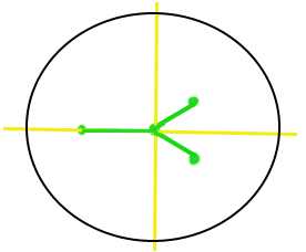
When color bars are displayed, the usual mushy blob is replaced by six sharp dots. These dots are supposed to fall into the boxes. Accomplish this by rotating the phase on the TBC until the dots line up with the boxes. (A hint: You'll also see two dimmer dots much closer to the center. These make a perfect 90 degree angle to each other. Orient them like this sideways vee < and you'll be in the ballpark.)
Signals from outside the studio also need to be aligned with the master studio sync generator. This is usually done when a remote camera or satellite feed is being used. The process is the same as for the VCR, and all adjustments are done to the TBC, not the remote camera. For this a synchronizer is used. In the past, this unit was separate from the TBC, but now they are most often combined into one.
Books about Television Technology and Production:
- Video Production Handbook General guide and overview of Profesional technique. In a sense, a condensation of the next book.
- The Technique of Television Production This very comprehensive book is possibly the best overview of technical television. It has been updated for the 90s, and is handy as reference, or as a textbook. It also covers the roles and interactions of the crew, scripting, and planning.
- Video Editing and Post Production: A Professional Guide This is more focused on the all the steps after the shooting stops.
Related links:
- Lenses and Lights.com ,
my regularly updated blog of camera and lighting articles, with tips, theory and tutorials.- Wikipedia article on NTSC Includes more complete technical details, and history.
- Loop Throughs and Terminations A very good article about looping and terminating video.
- The Blue Screen / Chroma Key Page
- Early history of NTSC The picture of the pennant above is from this site.
"The NTSC Pennant illustrates the NTSC concept of transmitting full color in large areas, two-color information (orange-cyan I axis) in medium sized areas, and only luminance information in small details"- Videotape Formats List
- The D/Vision Pro Non-Linear Editing Tips Page
eMail: bradford@seanet.com